|
8.b
DETAILED FACILITY PROGRAM
Using
the Summary Program as an index, a Detailed Facility Program is developed.
Prepared with the involvement of those who will be using and operating
the building, the Detailed Facility Program describes each functional
space in appropriate detail. It establishes design criteria and standards.
It reaffirms construction and project cost budget targets.
This
document will include general space descriptions, architectural characteristics,
building system characteristics, access and spatial relationships, and
special furnishings and equipment. See the sample page that follows.
Purpose
and Size
|
Space
ID#
|
S4
|
|
Space
Name
|
Intro
Science Lab
|
|
Purpose
|
Multipurpose
laboratory and discussion space for 24 students, for hands-on and
activity based learning; ongoing projects; short-term animal holding,
plant cultivation; lectures, demonstrations, and audio-visual (multi-media)
demonstrations.
|
|
Net
Assignable Square Feet (NASF)
|
1,700
|
|
Stations
|
24
lab stations AND 24 discussion stations
|
Architectural
Characteristics
|
Windows
|
Required,
operable, with darkening devices such as shades or blinds
|
|
Doors
|
3’-6"x7’,
with lock (on master key) and view panel
|
|
Floor
Finish
|
Resilient
flooring, stain resistant
|
|
Wall
Finish
|
Paint,
washable
|
|
Ceiling
Finish
|
Acoustic
surface
|
|
Ceiling
Height
|
10’
minimum (the more technically demanding the space the higher the
ceiling)
|
|
Acoustics
|
Standard
for this space category
|
Mechanical/Utility
Characteristics
|
Temperature
|
Standard
63Foto 76Fo
|
|
Room
or Zone Controls
|
Individual
room temperature control
|
|
Exhaust
to Outside
|
Fume
hood, minimum 4 ft. wide
|
|
Electrical
|
110V
1 Phase, ground; duplex outlets along walls; GFI outlets at each
work station near water
|
|
Lighting
|
Fluorescent
|
|
Plumbing
|
Hot
water, cold water, sinks, gas
|
|
Safety
|
Eyewash
and shower, fire blanket, extinguisher
|
|
|
Communication
Requirements
|
Communication:
Voice
|
Minimum
one port
|
|
Communication:
Data and Video
|
One
port at each lab workstation — student and teacher
|
|
|
Furniture
and Equipment
|
Demonstration
Table
|
Island
bench with sink, hot and cold water, gas, data port
|
|
Student
Seating
|
Stools
at benches and computer stations; 24 tablet arm chairs
|
|
Benches
|
Island,
peninsula, or wall bench at standing height; cabinets with shelves
and drawers below; cabinets with shelves above along walls; computer
tables at sitting height
|
|
Teachers
Desk
|
Teacher’s
desk and chair
|
|
Related
Equipment
|
Chalk
or white board
|
|
Demonstration
computer
|
|
Ceiling-mounted
projection screen
|
|
Audio-visual
equipment control cabinet
|
|
|
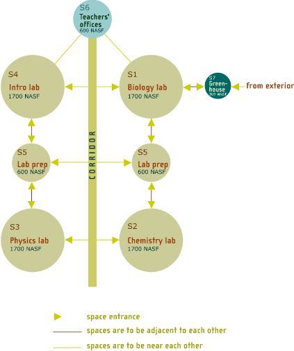
Another
useful program component is a space relationship diagram that graphically
shows required space adjacencies. See the sample below. This type of diagram
confirms the relationship of one space to another, and can be valuable
as a means for both user and architect to understand space adjacencies.

The
primary audience for the detailed facility program is the architect and
engineering team. For the school, this document clarifies expectations.
It also provides a management tool for reviewing designs and documents
at each step of the design and construction cycle to be sure that the
program requirements, the design, and the costs are in balance with each
other.
|

